

Select structural profiles based on their application, dimensions, load capacity, and the appropriate fastening method. This guide focuses on aluminum structural profiles with longitudinal grooves. The cut-to-length dimensions and the complete parts list are not finalized until after the selection process is complete. Therefore, if you order based solely on the external dimensions of a structure, you may end up with the wrong frame right from the start.
This guide walks you through the process from sketch to finalized order. To do this, we’ll break down a table frame—consisting of an upper frame, a center crossbar, and lower struts—into its individual parts. You’ll also learn why two 40 × 40 mm profiles can differ and what to look for when selecting accessories.
At rotec, you can find profiles and components for this purpose in the Aluminum Profile Shop. If the goal is to turn individual components into a complete solution, we’ll work with you to develop your project. Depending on the agreed-upon scope, we’ll also handle design, manufacturing, and on-site installation.
What are structural profiles, and what are they used for?
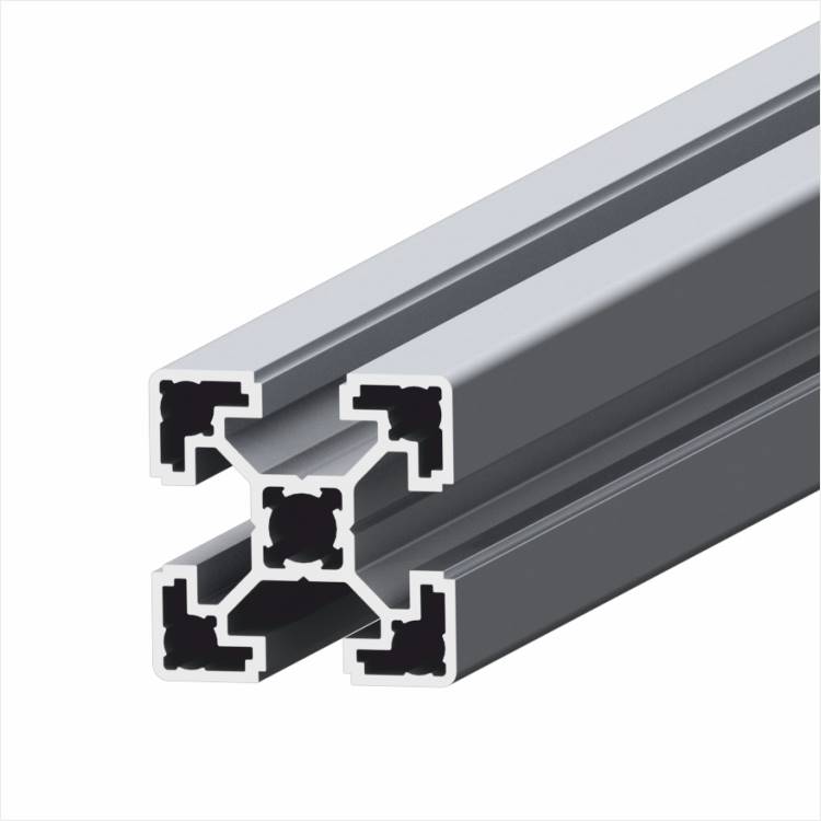
Structural profiles are used to build frames, racks, and other technical structures. Aluminum system profiles often have longitudinal slots. Suitable fasteners can be inserted into these slots to connect the profiles and attached components to one another.
This allows assemblies to be constructed in a modular fashion. For example, brackets or additional cross-braces can be added later using the appropriate fastening technology. Whether a modification is possible, however, depends on the available slots and accessible connections.
For workshops and production, therefore, the interaction of the components is what matters. A profile must be able to withstand the intended forces. At the same time, the connection, fastening, and environment must be suitable for the application. A suitable external dimension alone does not answer these questions.
Which structural profiles are right for your project?
Start by considering function, load, and installation conditions
First, describe what your design is intended to do. A frame for a lightweight sign has different requirements than a machine frame. It also makes a difference whether a load rests stationary or moves during operation.
Note the planned external dimensions, the clear spans, and the attachment points. Indicate where forces act and what degree of deflection the application allows. If adjacent components require precise positioning, even a slight deflection can be problematic.
The installation location is also part of the planning process. Therefore, check for access to tools, space for attachments, and whether the screws will be accessible later. If moisture, cleaning agents, or special environmental conditions are present, the material, surface, and fasteners must be appropriately selected.
Check the profile series and groove together
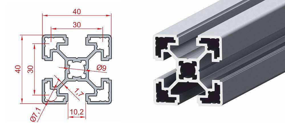
The designation "40 × 40 mm" refers primarily to the external profile dimensions. It does not specify either the internal geometry or all compatible accessories. Therefore, please compare the part number, groove specifications, and technical drawing.
This also applies even if existing parts look similar. A slot nut must match the slot geometry; in addition, its thread must match the screw. For end caps, on the other hand, what matters is the mounting at the end of the profile. The Overview of Aluminum System Profiles helps you narrow down your choices.
40 × 40 mm structural profiles: light or heavy?
Identical external dimensions do not necessarily mean the same stiffness or weight. This is illustrated by a comparison of two profiles from the rotec product line. Both have a 10-slot design, but differ in their material distribution.
| Characteristic | 40x40 Lightweight Profile | 40x40 Heavy-Duty Profile |
|---|---|---|
| Item Number | 1.1.10.040040.02 | 1.1.10.040040.01 |
| Groove size | 10 | 10 |
| Weight per meter | 1.24 kg/m | 1.64 kg/m |
| Moment of inertia Ix / Iy | 7.10 / 7.10 cm⁴ | 10.37 / 10.37 cm⁴ |
Source of product specifications: technical tables for 40x40 Lightweight Profile and 40x40 Heavy-Duty Profile, researched on September 12, 2026.
The moment of inertia describes how the cross-sectional area is distributed around a bending axis. For the same material and under otherwise identical conditions, a higher value indicates greater bending stiffness. However, this does not allow for the derivation of a general load-bearing capacity in kilograms.
The entire structure is a factor in your selection. This includes span, load distribution, connections, and supports. Therefore, a heavier design is not automatically the more economical solution. Similarly, a lightweight design is not sufficient simply because the frame appears small.
Tutorial: A Table Frame Made of Aluminum Profiles in 3D
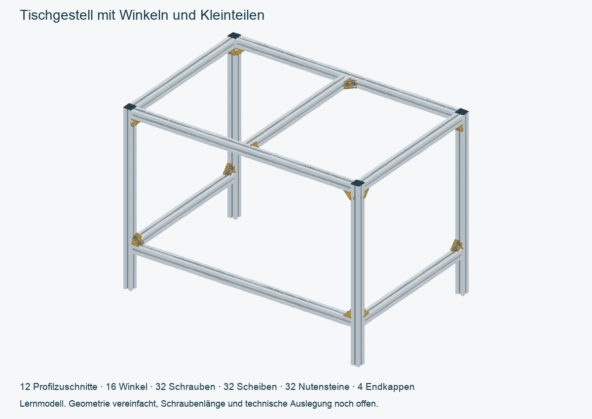
Our example shows a table frame with 1,200 mm wide, 800 mm deep, and 860 mm high. Four legs support an upper frame. An additional center crossbar divides the opening of the frame. At the bottom, two side struts and a rear longitudinal strut connect the legs. The front remains open at the bottom.
The frame consists of twelve cut-to-length profile pieces, each with a cross-section of 40 × 40 mm. The 40x40 profile with a 10-slot groove, item number 1.1.10.040040.02, serves as a reference. The detailed view also shows brackets, screws, washers, slotted nuts, and four upper end caps. The tabletop and adjustable legs are not yet included. The final working height will therefore depend on the frame and the selected add-ons.
This is a sample plan I created myself; it is not a completed client project. The profile shape is based on the shop drawing of the lightweight 40x40 profile with a 10-slot groove. Four longitudinal slots, four hollow chambers, and the central bore are visible. Internal contours and radii have been simplified. The connecting parts are assigned as a design suggestion. Screw length, strength, load-bearing capacity, and any necessary stiffeners still need to be determined. This illustration is intended to help understand the assembly, dimensions, and bill of materials.
Frame and Connecting Parts in 3D
Step 1: Understand the Function of the Components
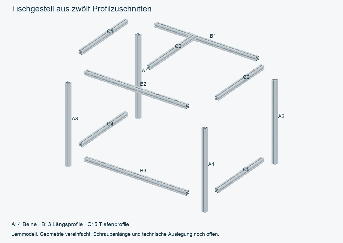
Legs A1 through A4 determine the frame height. At the top, B1 and B2 connect the legs lengthwise. C1 and C2 close off the frame on the sides. The center crossbar C3 is located between the two upper longitudinal profiles.
At the bottom, B3, C4, and C5 complete the structure. In the example, their lower edges are 180 mm above the bottom ends of the legs. The front underside has no longitudinal brace. This facilitates access but does not replace a stiffness and stability analysis.
Step 2: Calculate the cutting lengths based on the external dimensions
All four legs extend the full height of the frame. Therefore, each leg is cut to a length of 860 mm. The longitudinal profiles, on the other hand, are positioned between the legs. For these, you must subtract twice the profile width:
Longitudinal profiles: 1,200 mm − 2 × 40 mm = 1,120 mm
Accordingly, the length of the depth profiles is determined by the outer depth:
Depth profiles: 800 mm − 2 × 40 mm = 720 mm
The upper center crossmember C3 is also 720 mm long because it is located between the front and rear longitudinal members. Its center is 600 mm from the left outer edge. This creates two equally sized openings at the top, each measuring 540 × 720 mm.
This calculation assumes straight cuts and flush profile ends. Connectors that create a gap between the profiles will alter the dimensions. Therefore, determine the joint configuration and the connection system before placing your order.
Step 3: Create the profile bill of materials
Each item in the 3D view has a unique identifier. You can find this identifier in the bill of materials. Identical cut pieces can be grouped together for ordering, while the drawing shows their individual installation locations.
| Positions | Components | Number | Length per piece |
|---|---|---|---|
| A1 through A4 | Four legs | 4 | 860 mm |
| B1, B2 | Longitudinal profiles at the top, front, and rear | 2 | 1,120 mm |
| B3 | Longitudinal profile, bottom, rear | 1 | 1,120 mm |
| C1, C2 | Depth profiles at the top, left, and right | 2 | 720 mm |
| C3 | Upper center crossbar | 1 | 720 mm |
| C4, C5 | Depth profiles at the bottom, on the left, and on the right | 2 | 720 mm |
| Total length of finished profiles | 12 Profiles | 10,400 mm | |
In summary, the list includes four pieces measuring 860 mm, three pieces measuring 1,120 mm, and five pieces measuring 720 mm. The 10,400 mm measurement does not include any cutting losses or trimming allowances. The reference profile assigned in the learning model must be checked for the intended load before actual installation.
Step 4: Assign the connecting parts
The eight horizontal profiles have a total of 16 ends to be connected. For the educational model, a wide corner bracket is provided at each connection. For each bracket, the detailed view shows two M8 screws, two washers, and two T-slot nuts.
For reference, we use the 40x40 Wide Corner Joint, Groove 10 Version, Part Number 2.2.001.10.4040.33. The corresponding shop drawing shows a bracket measuring 37 × 37 × 37 mm with 9 mm-wide mounting holes. The 3D view provides a simplified illustration of its function.
At the joints between the frame profile and the leg, the angle on the upper frame lies below the horizontal profile. On the lower struts, it is located above. The two angles of the center crossbar C3, on the other hand, lie in the upper frame plane. There, they connect the side grooves of the profiles, which are at the same height.
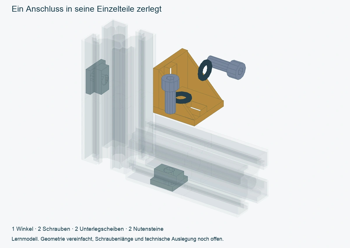
Parts List for Small Components in the Educational Model
| Position | Component | Quantity | Assignment and Checkpoint |
|---|---|---|---|
| W | 40x40 Wide Corner Joint, Groove 10 | 16 | 2.2.001.10.4040.33; one angle per connection |
| S | M8 hex socket screw | 32 | Length, head shape, stiffness, and part number still to be determined |
| U | Washer for M8 | 32 | Match the outer diameter, thickness, and design to the screw |
| N | T-slot nut, slot 10 / M8 | 32 | 2.1.006.10.08; two per bracket |
| K | 40x40 Profile Cover 10, Black | 4 | 2.3.001.4040.01; at the upper ends of the legs, provided that no other components are connected there |
The illustration therefore includes twelve profile sections and 116 small parts. The quantities correspond to the arrangement shown. Additional bracing or other connection designs may alter this parts list. Therefore, one angle bracket per connection is not a general design recommendation for every load.
The T-slot nuts for 10 mm slot with M8 must be inserted from the open end of the profile. With this design, they cannot be inserted from above after the fact. Your shop drawing specifies 20 × 19.4 × 10.5 mm and 9.7 mm for the narrow web. The assembly sequence must therefore take into account the profile ends that will later be concealed.
The four Upper profile covers for slot 10 Close off the open ends of the legs. According to the drawing, the cap is 3.3 mm thick. The frame alone is 860 mm high; with these top caps, the height of the prototype is 863.3 mm. This connection must be readjusted for a tabletop. The caps do not replace the adjustable feet.
Before placing an order, the exact screw length and the complete fastener design must be verified. The screws shown in the illustration are depicted for illustrative purposes only. Their depicted length is not a specification for ordering. The tightening torque, clearance, and suitability of all parts for the application must also be compatible.
What additional items should be included in the order?
Select Connectors, Screws, and T-nuts Together
Consider each connection as a single unit. First, check the profile matching on the connector. Next, verify the screw thread, the required screw length, and the appropriate nut. Also take into account the component thicknesses and the intended screw-in depth.
The installation sequence can also influence your choice. Some slotted nuts require access from the end of the profile, while other designs allow for installation at a later stage. Check this feature for the specific item before adjacent parts block access. The following provides an initial guide: Joining Technology for Aluminum System Profiles.
Don't forget the end caps and attachments
Open profile ends can be fitted with matching end caps. For table frames, special attention should be paid to the connections at the ends of the legs. These areas may be designed to accommodate feet, tabletop mounts, or other components. End caps should only be used in areas that actually remain free for that purpose.
Select the cap that matches the specific profile cross-section. An identical outer dimension is not always sufficient. The Profile Caps in the rotec Product Line differ, among other things, in terms of profile and system assignment.
You should also plan how the frame will be mounted later. Wall brackets, feet, casters, or machine connections serve different purposes. Therefore, they should not be included in the bill of materials until the installation situation and load requirements have been determined.
Add custom-made side panels to structural profiles
An open-frame profile rack can be assembled into a unit with matching side panels, a back panel, or shelving. rotec can laser-cut the required sheet metal panels to size in-house. We tailor the contours, cutouts, and mounting holes to your profile frame. Our article explains how a drawing is turned into the right component: Laser Cutting and Custom Laser-Cut Parts.
Plan the cladding and frame together. The material, sheet metal thickness, fastening points, and accessible screws all influence the design. If angled edges or mounting tabs are required, we supplement the cut-to-size sheet with Bending and Folding Sheet Metal. Our guide describes additional processing steps and the assembly of subassemblies Sheet Metal Fabrication and Metalworking in Berlin.
If the cladding is to remain open and breathable, a suitably framed infill made of Custom-made expanded metal or expanded mesh are suitable. We tailor the material, mesh pattern, and fastenings to the specific application. To help us process your request, please provide a sketch of the frame, the desired cladding areas, and the locations of the required openings.
Order Custom-Made Structural Profiles: Cutting and Accessories
A clear cutting list prevents the need for follow-up questions and makes it easier to verify the order upon receipt of goods. For each item, specify the selected profile, the finished length in millimeters, and the quantity. Also include any special processing requirements, if your project calls for them.
In this example, you can combine the twelve cut pieces into three order items. However, keep the item assignments A1 through C5 in the drawing. This will ensure that the assembly remains traceable.
If you order pre-cut pieces, do not simply add a standard sawing allowance to the desired finished dimension. If you are machining bar stock yourself, however, you must factor cutting losses into your material planning. Be sure to explicitly specify any required length tolerances and additional machining operations.
Before finalizing the order, be sure to review the details of the specific quote. This includes cutting options, scope of delivery, additional costs, and delivery date. If there are multiple profile types or a wide range of accessories, it’s a good idea to submit a single project request to ensure that all items are clearly compatible.
This is how the bill of materials is turned into a traceable assembly plan
Sort the parts by location before assembly. Then compare the profile type, length, and accessories with the approved drawing. This will help you identify any discrepancies before an assembly ends up with hard-to-reach areas.
For the table frame, you can start by preparing the two side panels, provided that the selected connectors allow for this assembly sequence. Next, install the longitudinal profiles and the upper center crossbar. As you work, check the external dimensions, joints, and right angles. Comparing the diagonals of individual frame planes helps ensure dimensional accuracy.
The final tightening of the fasteners must follow the specifications of the selected system. Generic torque values are not suitable for this purpose. The installation at the site must also be appropriate for the actual application. Before use, it is particularly important to check the connections, bracing, stability, and the actual load.
With this information, rotec can review your project
You don't need a fully developed design for the initial meeting. A clear sketch showing the intended function is already a good starting point. The following information will help us develop a concrete plan:
- Application and Location of Use of the Design
- External dimensions, clear openings, and available installation spaces
- Loads, load positions, and possible movements
- Desired profiles or existing system components
- Quantity, as well as required cut pieces and machining operations
- Planned add-ons, mounting points, and interfaces
- Desired Scope of Planning, Manufacturing, and Installation
- Proposed schedule and existing drawings or CAD documents
This will help determine whether you need individual components or a jointly developed assembly. You can learn more about the implementation in the article Aluminium profile constructions: Planning, manufacturing and installation. You can find more technical articles in the section Structural profiles.
Frequently Asked Questions About Structural Profiles
Which structural profiles are suitable for a table frame?
This depends on dimensions, spans, loads, and connection methods. Our example uses the lightweight 40 × 40 mm profile with a 10-series groove as a reference. This does not, however, constitute approval for a specific load or load-bearing capacity.
Why are the longitudinal profiles shorter than the overall dimension?
In this example, the longitudinal profiles are positioned between two legs, each 40 mm wide. Therefore, with an outer width of 1,200 mm, the cut length is exactly 1,120 mm. If the joints are arranged differently, the calculation changes.
How many profile cuts are needed for the rack shown?
The learning model consists of twelve cut pieces: four legs measuring 860 mm, three longitudinal profiles measuring 1,120 mm, and five depth profiles measuring 720 mm. Their total finished length is 10,400 mm, with no material waste.
Is the specified rack height already the working height?
No. The 860 mm refers to the frame profile alone. The dimensions specified in the learning model upper caps increase the measurement to 863.3 mm. To determine the final working height, you must take into account the tabletop, the legs, and the chosen connection method.
Can I order the parts list directly as a complete kit?
This article includes the profile cut lists and a supplementary bill of materials for the small parts. Before placing an order, be sure to check the screw length, head shape, strength, washers, and the overall fastener design. The tabletop, legs, and any bracing must also be selected based on the intended use.
Are profiles of the same size compatible with each other?
Identical external dimensions do not guarantee compatibility. Check the profile series, groove geometry, and the assignment of the individual connecting parts. For existing components, part numbers and cross-sectional drawings can help with the matching process.
Do I need to add a seam allowance to pre-cut pieces?
Specify the required finished dimension and agree on the necessary tolerances. A flat-rate allowance for the saw cut width is not included in the finished dimension. If you are cutting the material yourself from bar stock, you must account for cutting losses when planning your material.
How much weight can the table frame shown here support?
No permissible load capacity has been specified for this learning model. To provide a reliable load capacity estimate, information such as the specific profile variant, connections, load positions, tabletop, and installation configuration is required. The 3D view illustrates the structure but does not replace this design analysis.
Can Rotec design, manufacture, and install the frame on site?
Yes. rotec can develop projects in collaboration with you and, depending on the agreed scope, design, manufacture, and install them on site. The contact person for technical advice on designs is Dipl. Ing. Ferhat Macar at 030 789039-46 and f.macar@rotec-berlin.de.
Your sketch is the first step toward the right design
To make the right selection, the profile, dimensions, and connections must all match. The table frame also illustrates why external dimensions cannot simply be used as-is for cut-to-length pieces. With a clear drawing and labeled individual parts, you can create a reliable foundation for further planning.
Sale of Cut-to-Size Pieces and Structural Profiles
Mercan Özsoy is your contact person for the sale of custom-cut pieces and structural profiles. Please send your inquiry, including profile specifications, cut lengths, and quantities.
Phone: 030 789039-80
Email: m.oezsoy@rotec-berlin.de
Request Custom Cuts and Structural Profiles
Technical Consulting for Structures
Ferhat Macar, B.S. in Engineering is your point of contact for technical advice on designs. Send us your sketch or drawing and describe the intended application. Together, we’ll determine the appropriate components and the desired scope of services. rotec can support you every step of the way—from development and manufacturing to on-site installation.
Phone: 030 789039-46
Email: f.macar@rotec-berlin.de


 EN
EN  DE
DE  ES
ES  FR
FR  IT
IT  NL
NL  PL
PL  TR
TR