
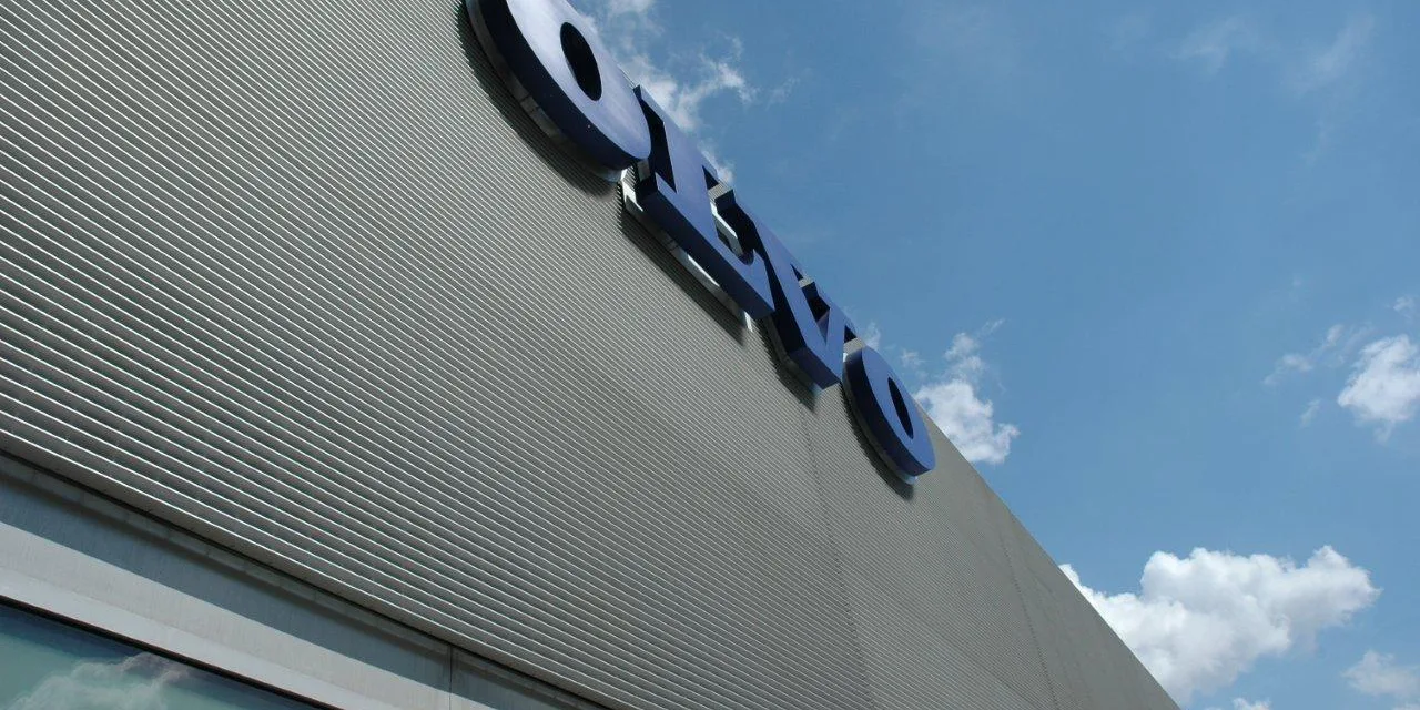
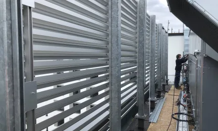
"Berlin" facade grating at the Volvo dealership: The view from below shows the spatial depth of the aluminum bars. Image source: rotec.
The Berlin-Style Facade Grating The rotec system is an aluminum grating with hydraulically pressed bar intersections. As a result, it requires no welded joints at those points and does not need a perimeter frame to secure the joints. This allows for the creation of an open facade whose grid appears to continue visually beyond the boundaries of the individual elements.
Element sizes up to 6,000 × 1,284 mm allow for generous facade divisions. In addition, anodizing or powder coating can be used to achieve the desired appearance. The Berlin type is used on facades, stair towers, and as suspended grating ceilings. For designers and facade contractors, the direction of the bars, the joint pattern, and the fastening method are therefore particularly important.
Discuss a facade project with rotec
A sketch or project description can help you get started, even if some technical details haven't been finalized yet.
The Berlin Model in Action: Facades, Stair Towers, and Ceilings
A car dealership in Berlin, a parking garage facade in Freiberg, and a stair tower cladding showcase the "Berlin" type in various installation settings. In addition, rotec documents 3,200 m² of aluminum grating for the ceilings at Stuttgart's train stations. The original images and the film featuring Karl Marx help illustrate the construction and the visual impact of the facades.
What Sets the "Berlin" Type Facade Grating Apart
Hydraulically pressed joints
In the Berlin type, the load-bearing bars pass through the openings in the infill bars. The profiles are then permanently joined together using a hydraulic pressing process. As a result, the intersection points do not require welded joints. rotec describes this design on the Product page for aluminum facade grating, Berlin model.
Support bars run in the intended direction of support, while infill bars connect them across that direction. In the Berlin model, there are no welds at their intersections. As a result, the clean profile structure remains visible even when viewed up close.

Continuous mesh pattern without a border around the edges
The Berlin type does not require a border to secure its compressed nodes. This allows the grid to visually extend across adjacent grid areas. The rotec PDF Advantages of Aluminum Facade Grates describes the permanent knot connections and the coordinated mesh pattern.
When adjacent elements are joined together, half-panels at the joints visually complement each other to form a complete panel. With precise alignment, the joint between the elements is largely concealed within the grid. This creates a cohesive facade appearance.
For this to work, the direction of the bars, the edge clearances, and the panel joints must all align properly. Half-bar fillers form the visible transition. However, they do not mechanically connect the adjacent grating panels to one another. Each panel therefore requires its designated connections.
Video: Karl Marx Explains the "Berlin-Style" Facade Grating
In the rotec video, Karl Marx explains the pressing process as well as the options for surface finishes and fastening methods. In addition, project footage demonstrates how the orientation of the bars and the viewing angle affect the transparency of a grid facade.
These sections help you find specific information:
- Starting at 1:54: Visible welds on conventional gratings and their effect on the surface.
- Starting at 2:21: Berlin type with compressed joints, long elements, and a design without edge trim.
- Starting at 3:10: Different perspectives of a parking garage facade with vertical support bars.
- Starting at 4:31: Attachment to the substructure using welded-in mounting plates.
The first comparative section of the film focuses on conventional steel gratings, including hot-dip galvanized ones. Its close-ups show visible welds, even on a color-coated sample. In contrast, the subsequent comparison of aluminum focuses on the specific materials and manufacturing processes described in each case.
The Berlin Model Compared to Welded Aluminum Grates
The following tables compare the rotec Berlin-Style Facade Grating with a Conventional aluminum grate with welded crossbars.
The comparison table can be moved to the side.
Design, Interface, and Element Size
| Characteristic | rotec Berlin-Style Facade Grating | Welded Aluminum Grate |
|---|---|---|
| Element Joint and Grid | Half-length filler strips visually join together at the seam to form a complete strip. When precisely aligned, the joint is barely noticeable. | Visibility of the joint depends on the edge design, joint width, and installation. |
| Border edging | No edging is required to secure the compressed joints. | Usually framed. Special frameless designs require a separate structural review. |
| Visible surface | Regular profile structure with no welds at the junctions. | A paint coating does not automatically eliminate weld lines. They may remain visible on the facade. |
| Surface | Can be decoratively anodized or powder-coated; a satin-matte metallic finish is possible. | Anodizing can reveal color differences at welds. The appearance also depends on post-processing and surface treatment. |
| Warp and Flatness | Extruded profiles and pressing without welding heat result in a rust surface with very little warping. | Heat from welding and cooling can cause warping. Manufacturing processes and, if necessary, straightening affect flatness. |
| Element Formats | Up to 6,000 × 1,284 mm. Support spacing must be verified separately. | rotec recommendation for this facade design: no more than 2 m² per element. No general manufacturing limit. |
Machining, Joints, and Load-Bearing Performance
| Characteristic | rotec Berlin-Style Facade Grating | Welded Aluminum Grate |
|---|---|---|
| Excerpts | Each intersection point is crimped. This makes cutting easier; the remaining bars and connections must be inspected. | That is also possible. Cut-through welded joints may require additional fasteners or reinforcements. |
| Knot connection | Hydraulically pressed bar joints with no welds. | The bars are joined by welding at their intersections. |
| Shear field effect | The pinned joints allow shear forces to be transmitted within the grating plane. Verification is required for the specific design. | Welded joints can also transmit shear forces. The key components are nodes, members, and connections. |
| Durability of the Knots | There are no welds at the pressed bar junctions. This eliminates weld failure as a possible cause of damage in those areas. | Repeated stress can cause fatigue cracks that may lead to fracture. The design, construction, and load are key factors. |
| Material | AlMgSi0.5 F22. | As stated in the product data sheet. |
| Suitability for Facades and Design Calculations | Designed for open facades with a continuous grid. Project-specific sizing is required. | Not recommended by rotec for frameless facade installations. Suitability and load-bearing capacity depend on the specific design. |
Why Manufacturing and Surface Finishing Go Hand in Hand
Extruded profiles and hydraulic pressing result in a grid surface with very little distortion. When joining the nodes, there is no heat generated by welding and, therefore, no welding-induced distortion at those points. However, additional welding work on connection plates must be taken into account separately.
For a visible facade, the surface finish after the final treatment is also important. A paint coating does not automatically eliminate weld lines; during anodizing, welded areas may stand out in color. Therefore, post-processing and surface treatment methods also influence the final result. With the Berlin model, however, these welds at the bar intersections are eliminated by the design itself.
Excerpts: Nodes remain connected; path lengths change
In cutouts, the compressed nodes not affected by the cut remain firmly connected. This facilitates, for example, cutouts for penetrations and connections. However, a cutout may interrupt load-bearing members and thereby alter the force transfer to the support. Its location and size, along with the fasteners, must therefore be included in the approval designation.
What does the "shear field effect" mean in the context of facade grating?
The shear field effect describes the transfer of forces within the grid plane. In this process, the bars and nodes counteract lateral displacement of the grid. The "Advantages" PDF highlights the permanent connection between the main and infill bars achieved through the hydraulic pressing process.
The extent of this effect depends on the profiles, joints, element geometry, and connections. However, the stiffness of the grating does not automatically mean that it contributes to the building’s bracing. A separate, project-specific verification is required for this.
Durability of Knot Connections
At pressed bar junctions, weld failure is not a potential cause of damage. In welded joints, however, repeated loading can cause fatigue cracks that may lead to failure. Whether this occurs depends on the load, design, and quality of workmanship—not solely on the number of years in service. Even with the Berlin type, profiles and connections must be designed to withstand the intended loads.
Which version is right for the task?
For large-format facades with a uniform grid and frameless elements, rotec recommends the Berlin-type facade grating. When using welded aluminum gratings, designers should carefully consider how the edge design, surface quality, and element layout align with their design.
The "Advantages" PDF uses an AlMg3 F18 aluminum press-formed grating as a comparison example. Its material specifications therefore do not apply to all welded aluminum gratings. For conclusions regarding weight, load-bearing capacity, and service life, the comparison therefore requires specific data for the respective designs.
Send the facade drawing for technical review
You can attach your drawing or the scope of work to the request form. You may upload up to five files, each no larger than 12 MB. Specify "Type Berlin" and mark the points that you would like rotec to coordinate with you.
Dimensions, Grid Spacing, and Finishes of the "Berlin" Type Facade Grating
Maximum panel size: 6,000 × 1,284 mm
The Berlin type is suitable for element sizes up to 6,000 × 1,284 mm feasible. This means that a long element can reduce the number of visible divisions. At the same time, transportation, delivery, and installation must be compatible with the selected size.
The element length does not describe a span that can be freely bridged. This is because it depends, among other things, on member cross-sections, supports, and loads. A drawing should therefore show not only the external dimensions but also the intended fastening locations.
In cases of narrow access routes or limited installation areas, smaller sections may be more practical. Therefore, check the transport route before finalizing the layout of the elements.
Which grids are specified in the technical documentation
The Technical Catalog for Rotec Facade Grates, PDF includes separate technical data sheets for the Berlin model. The following overview summarizes this information.
| Information | Berlin-Style Facade Grating |
|---|---|
| Material | AlMgSi0.5 F22 |
| Maximum element size | 6,000 × 1,284 mm (length × width) |
| Mesh Sizes | 35.46 × 33 mm; 35.46 × 50 mm; 35.46 × 66 mm; 35.46 × 100 mm |
| Cross-Sections of Load-Bearing Members | Technical Data Sheet, Part 1: 30 × 3 to 70 × 3 mm, in 5-mm increments in height. |
| Other rod thicknesses | The technical data sheet, Part 2, also lists 4 and 5 mm. Determine the specific design for the project. |
| Surfaces | Pickling, anodizing, or powder coating. |
| Anodized Colors | C0 natural color; C31 through C34 in bronze shades; C35 black. Additional decorative colors available upon request. |
| Other Design Options | Combination with facade profiles and stair tread designs. Walkable applications require appropriate design. |
The technical variants are from the July 2018 catalog. The maximum element size is 6,000 × 1,284 mm, as confirmed by Karl Marx on September 6, 2026. Therefore, please verify the currently available combination of grid, bar height, and bar thickness before placing your order.
Design Data Sheet for the Berlin Model
Download the Design Data Sheet for the "Berlin" Type Facade Grating (PDF)
The planning data sheet consolidates element dimensions, profile construction, finishes, and installation instructions. It also shows the maximum element outline and practical installation details. Dimensional connection details are created for each specific project, as the substructure and loads determine the design.
In drawings, it is also important to distinguish between mesh size and mesh spacing. Mesh size refers to the clear opening. Mesh spacing, on the other hand, describes the distance from the center of one bar to the center of the next. The rotec Glossary of Grating Terms explains these terms.
Therefore, both directions should be clearly dimensioned in an order. Also include the direction of the support bars and the desired bar height. This allows the design to be reliably verified against the approval designation.
Aluminum, anodized aluminum, and powder coating
"Typ Berlin" consists of AlMgSi0.5 F22. The material and the profile surfaces are suitable for decorative anodizing. This allows for a uniform, satin-matte metallic finish. Alternatively, the surface can be powder-coated. The rotec Overview of Aluminum Grating explains the different surface finishes.
To ensure a cohesive color scheme, visible brackets and substructures should be incorporated into the design. Even a recessed mounting can be noticeable when viewed from the side. Therefore, coordinate the color and surface finish using a sample.
Cutouts and mounting plates should be finalized before the final surface treatment. This prevents subsequent machining from damaging the finished visible surface.
Designing Facades: View Direction and Bar Alignment
Horizontal Lines at the Car Dealership
The Volvo dealership in Berlin features a design with horizontal support members. This gives the facade a distinctly horizontal structure. At the same time, the grid structure remains recognizable as the foreground layer. rotec documents this project along with other examples in the Reference Overview: „Grating for Facades“.
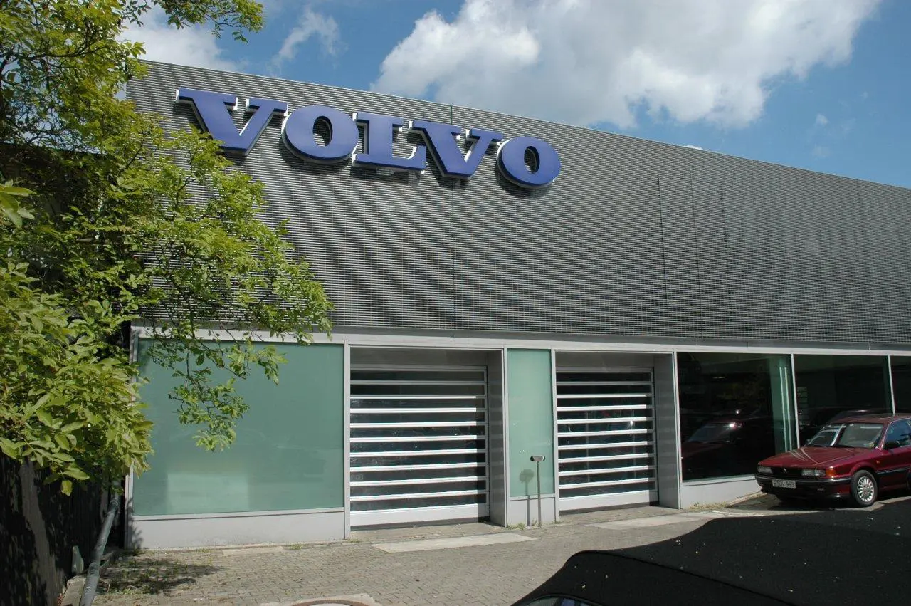
For similar designs, it’s worth comparing multiple views. From the front, a lattice surface may appear open, while a lower viewing angle makes the slats appear more overlapping. Therefore, prototyping and visualization should also take into account typical paths around the building.
The corners of buildings and doors determine whether the horizontal division continues. Therefore, be sure to draw in the edge sections and terminations as well.
Vertical Layout of the Parking Garage
In the parking garage facade in Freiberg documented by rotec, the load-bearing members run vertically. This significantly alters the character of the grid structure. The open exterior shell allows for both views into and out of the building.

When planning a parking garage, however, the design, ventilation, and necessary safety features must all be coordinated. In this context, the actual clear opening area deserves special attention, as substructures or additional fixtures can affect the available cross-sectional area.
A separate horizontal barrier is also visible in front of the grid facade. The project design must therefore clearly specify which components are intended to withstand fall or impact loads.
Coordinate Privacy and Sun Protection Effectively
The Berlin model can divide facade areas and restrict the view depending on the geometry and line of sight. To achieve the desired level of privacy, the relevant vantage points must therefore be determined. For example, it is crucial to determine whether the view is being assessed from the sidewalk, from a neighboring building, or from inside a building.
Facade orientation and the sun's position also play a role in shading. A sample provides a visual impression, while technical planning evaluates the desired effect. This results in reliable specifications for the grid, slat height, and installation position.
When it comes to roof systems, privacy protection, unobstructed airflow, and maintenance access go hand in hand. The Project Report on Roof Enclosures for Air Conditioning Systems explains these planning considerations using an aluminum slat plant in Frankfurt as an example.
If there are additional requirements for rain protection or air circulation, other facade systems may also be considered. The article on Renson Linius Louvered Facades by rotec To that end, it offers project-specific solutions featuring aluminum fins.
Reference: Stairwell Cladding, Berlin Model
With the Stairwell cladding with "Berlin" type facade grating The aluminum structure encloses an exterior staircase. The published project report mentions a mesh of 33 × 100 mm. This description refers to the version available there.
The lattice cladding visually unifies several stories, while the staircase structure behind it remains visible.

In a comparable staircase design, landings, doorways, and anchorage levels determine the division of elements. These points should therefore be included in the facade plan at an early stage.
If the cladding is also to serve as fall protection, this function must be explicitly included in the design. The customer must therefore obtain the necessary tests and certifications. These certifications must take into account the entire component, including its fastenings and substructure. The selected mesh alone does not, therefore, prove its suitability as a fall protection system.
Installation of the "Berlin" Type Facade Grating
Welded mounting plates for discreet installation
rotec has, with welded mounting plates We've had the best results with this approach. The plates serve as connecting plates and allow for easy screw-based installation onto the substructure. Because they are located within the grid, the fasteners are barely visible from the facade when properly arranged.
In addition, depending on the model, slotted holes may be part of the connection detail. The photo shows a welded mounting plate with a screw inserted.

The connecting plate shown in the picture is welded, while the bar intersections are pressed together. An additional edge trim, if desired, may also require welding. The description „without welded joints at the intersections“ therefore specifically refers to the grid structure.
Mounting Spacing and Connection Planning
rotec varies depending on the thickness of the support bar Spacing of 1,500 to 2,000 mm between the welded mounting plates . The final layout also depends on the geometry of the elements, the load, and the substructure.
Therefore, specify the fastening locations in the drawing before manufacturing begins. Be sure to take into account the accessibility of the screw locations so that installation on the building can proceed as planned.
In addition, the design must account for movement and assembly tolerances. Designers therefore specify fixed and movable connection points in accordance with the structural concept. Different adjacent materials must therefore also be included in the detailed review.
Other factors that affect the design include building height, installation location, and wind loads. This also applies to an open lattice structure.
Stuttgart 21 Reference: "Berlin" Type Suspended Ceiling
The "Berlin" type of facade grating is also used overhead. For the Stuttgart 21 Project Report rotec supplied the documented station ceilings 3,200 m² Aluminum grating.
A mesh made of 35.4 × 100 mm and support bars 40/3 mm. This included an EV1 anodized finish and a specially adapted mounting system. According to the project report, rotec developed the connector in collaboration with KREBS+KIEFER.
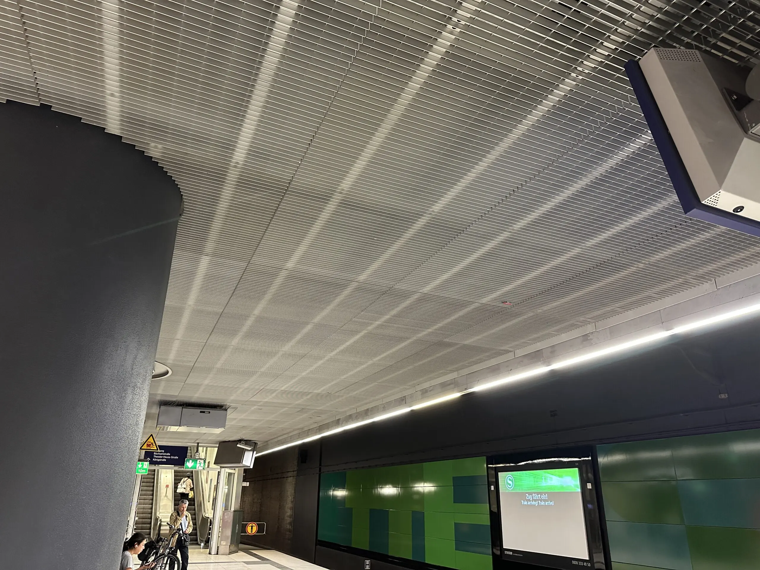
What the Ceiling Project Reveals About the Planning Process
The project combines a large-scale ceiling grid with custom-designed connectors. For similar projects, therefore, the visible surface and the mounting system must be planned together.
Therefore, be sure to include lighting fixtures, mechanical and electrical components, and access panels in the ceiling plan early on. Also, determine which areas must remain accessible for maintenance of the installations.
More Aluminum Facades: Type A Projects
On CityCube Berlin documented by rotec 272 m² Aluminum facade grilles with a dark powder-coated finish. The Rosenheim Bike Station shows, on the other hand, 199 m² Aluminum facade grating in RAL 9007. However, the respective reference pages refer to the grating used as Type A.
They thus complement the design examples. However, when making technical selections, their product designations must be taken into account separately.
How to Prepare a Request for Rotec
Consulting and Project Management at rotec
rotec Berlin Metalltechnik GmbH brings Experience since 1982 into the consultation process for metal products and construction projects. For the Berlin model, the technical coordination specifically covers the grid layout, surface finish, and fastening details. The Stuttgart project also demonstrates collaboration with specialist designers to develop a customized connection solution.
In your request, please also describe the scope of delivery you require. Be sure to explicitly specify who will be responsible for the substructure, fasteners, and installation. This will allow you to allocate the contributions of the participating companies before placing the order.
This information gives the project concrete form
A dimensioned view makes it easier to get started. If possible, include a cross-section through the grid and substructure. The following information will also help with coordination:
- Location: Facade, stair tower, parking garage, sunshade, or suspended ceiling.
- Dimensions: Element length, element width, number of elements, and total area.
- Lattice Structure: Desired grid, direction of the support members, as well as the height and thickness of the members, if already specified.
- Design: Available with or without edging, joint patterns, and visible trim.
- Surface: Anodized finish or coating, color shade, and existing sample specifications.
- Connections: Material and location of the substructure, as well as existing fastening details.
- Requirements: Intended loads, required documentation, connections, and, if applicable, protective functions.
- Processing: Delivery location, delivery options, preferred date, and planned installation schedule.
If there are still some unresolved issues, please indicate them in your inquiry. This will allow us to focus our consultation specifically on the decisions that need to be made.
Factors That Affect the Effort Required
In addition to the area, the layout of the elements, connection details, and surface finish determine the scope of work. Additional cutouts or a large number of different element sizes also increase the need for coordination. Therefore, a quote should be based on as clear a project description as possible.
Compare quotes for the same scope of services: including the agreed-upon fasteners, coating, packaging, and shipping services.
Quality and Project-Specific Documentation
What documentation is required for this specific component?
The required technical documentation depends on the intended application and the specific design. This includes the grating, its fastenings, and the substructure. Therefore, be sure to specify the required documentation during the project planning phase.
The customer is always responsible for obtaining the required inspections and documentation regarding fall protection. Therefore, general product information or company certifications do not replace these project-specific documents.
Quality Management and Welding Technology at rotec
The rotec Certificate Overview makes company records available to planners and clients. The Certificate in accordance with DIN EN ISO 9001:2015 documents the quality management system within the specified scope. The Certificate in accordance with DIN EN ISO 3834-3 relates to welding quality requirements.
These company certifications thus assist in the selection of suppliers. However, their respective scope of application remains the decisive factor. This does not imply certification of the pressed joints.
Frequently Asked Questions About the "Berlin" Type Facade Grating
How wide is the "Berlin" type facade grating?
The maximum element size is 6,000 × 1,284 mm, i.e., 6,000 mm in length and 1,284 mm in width. To place a specific order, the grid and the connections must also be specified.
What are the recommended spacing distances for the mounting plates?
rotec recommends spacing of 1,500 to 2,000 mm between the welded mounting plates. The exact arrangement also depends on the element geometry, load, and substructure. Therefore, the mounting positions must be included in the project drawing.
Can the Berlin model be made without a border?
Yes. The Berlin type does not require an edge trim to secure the compressed joints. Half-width filler bars can visually form a complete profile at the element joints. To achieve this, the joints, bar orientation, and alignment of adjacent elements must match.
Can cutouts be included in a Berlin-style grate?
Yes. Because the intersection points are crimped, the nodes not affected by the cut remain connected. The size, location, and remaining rods must still be checked for structural integrity.
Are the bar junctions welded?
No. In the Berlin model, a hydraulic pressing process joins the bars at their intersections. However, welded joints can be used for connection plates or to create a desired edge trim.
Is the Berlin type generally more durable than a welded aluminum grate?
There is no one-size-fits-all answer. This is because load-bearing capacity depends, among other things, on geometry, material, supports, and connections. Therefore, a comparison requires specific technical data for both designs.
Does a length of 6,000 mm also mean a clear span of 6,000 mm?
No. The dimension indicates a possible element length. The permissible distances between supports, on the other hand, are determined by the specific design calculations.
Can the color be matched to the rest of the facade?
Yes, powder coating allows you to match colors. Anodizing is also an option. Therefore, use samples to ensure the desired look matches the surrounding materials.
What orientation should the facade design specify?
The direction of the bars influences the line pattern, transparency, and visual impact. Therefore, determine this direction along with the grid, installation orientation, and typical sightlines.
Is the Berlin model suitable for suspended ceilings?
Yes, the documented project in Stuttgart demonstrates such an application. However, the mounting method and other requirements must be appropriate for the specific ceiling.
Can a facade design also serve as a maintenance platform?
A walkable application requires a design specifically intended for that purpose. rotec lists maintenance platforms and walkways as possible applications. Therefore, walkability and applicable loads should be specified in the initial inquiry.
What documents does rotec need to provide a quote?
Dimensional views, cross-sections, quantities, and surface specifications are helpful. Also include the intended substructure and the requirements for the component.
Who is responsible for obtaining the fall protection inspections?
The customer must always obtain the necessary inspections and documentation regarding fall protection. These must cover the specific design, including fastenings and the supporting structure. Therefore, a reference photo alone does not prove that the system is suitable as fall protection for a new construction project.
Request a quote for Berlin-style facade grating for your project
The Berlin type combines extruded aluminum profiles with large panel sizes and a design without edge trim to secure the joints. This creates open facade designs with a visually continuous grid. The projects shown here illustrate, for example, its use on facades, stair towers, and ceilings.
Send your drawing, sketch, or specifications to rotec. Please include the location, dimensions, and desired finish. Highlight any open questions so that our consultation can focus on the areas where your project needs the next decision.


 EN
 DE
 ES
 FR
 IT
 NL
 PL
 TR